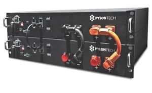
Pylontech Battery
The Pylontech component allows you to pull data from Pylontech Batteries into ESPHome. It uses UART for communication.
Once configured, you can use sensors as described below for your projects.

Hardware Setup
You can connect to Pylontech Batteries using the port labeled “Console”. Any connections via CAN or RS485 (e.g. to an inverter) are untouched and remain functional.
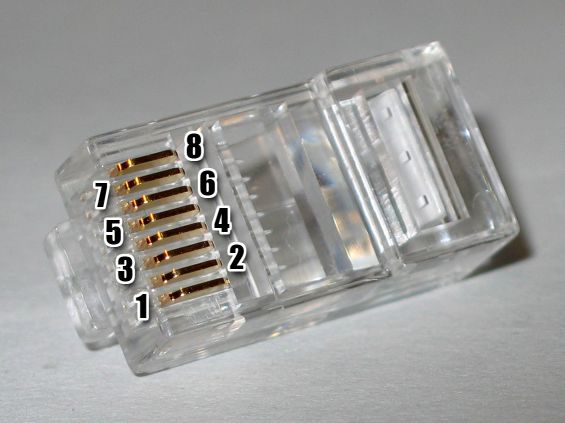
The console port offers a RS232 interface using a RJ11 or RJ45 connector. The voltage levels are not TTL-compatible. A RS232 transceiver must be placed between the Batteries and the ESPHome device. MAX3232-based transceivers have been tested and work well.
If you have multiple batteries you need to connect to the master battery’s console port.
Pylontech RJ45 Console Port (US2000C, US3000C, US5000C)
| RJ45 Pin | TIA-568B Color | TIA-568A Color | Function | Connect to |
|---|---|---|---|---|
| 3 | White/Green | White/Orange | Pylontech TX | ESPHome RX via transceiver |
| 6 | Green | Orange | Pylontech RX | ESPHome TX via transceiver |
| 8 | Brown | Brown | GND | GND |

Pylontech RJ11 Console Pinout (US2000B, US2000)
| RJ11 Pin | Function | Connect to |
|---|---|---|
| 2 | Pylontech RX | ESPHome TX via transceiver |
| 3 | Pylontech TX | ESPHome RX via transceiver |
| 4 | GND | GND |
Component/Hub
# Example configuration entry
pylontech:
Configuration variables:
- id (Required, ID): The id to use for this Pylontech component.
- uart_id (Optional): The uart Bus ID
- update_interval (Optional, Time): The interval to check the sensor. Defaults to
60s.
Sensor
All values are reported for every Pylontech battery individually.
# Example configuration entry
sensor:
  - platform: pylontech
    battery: 1

    voltage:
      name: "Battery1 Voltage"
    current:
      name: "Battery1 Current"
    coulomb:
      name: "Battery1 State of Charge"
Configuration variables:
- pylontech_id (Optional): Manually specify the ID of the pylontech instance if there are multiple.
- battery (Required): Which battery to monitor. 1 stands for the main battery, 2..16 for child batteries.
- voltage (Optional): Voltage of the battery. All options from Sensor.
- current (Optional): Current flowing into the battery. Negative when discharging. All options from Sensor.
- coulomb (Optional): State of Charge in percent. All options from Sensor.
- temperature (Optional): Temperature. All options from Sensor.
- temperature_low (Optional): Historic minimum temperature. All options from Sensor.
- temperature_high (Optional): Historic maximum temperature. All options from Sensor.
- voltage_low (Optional): Voltage of the lowest cell. All options from Sensor.
- voltage_high (Optional): Voltage of the highest cell. All options from Sensor.
- mos_temperature (Optional): Temperature of the mosfets. All options from Sensor.
Text Sensor
# Example configuration entry
text_sensor:
  - platform: pylontech
    pylontech_id: pylontech0
    battery: 1

    base_state:
      id: bat1_base_state
      name: "Battery1 Base State"
Configuration variables:
- pylontech_id (Optional): Manually specify the ID of the pylontech instance if there are multiple.
- battery (Required): Which battery to monitor. 1 stands for the main battery, 2..16 for child batteries.
- base_state (Optional): Base state. Usually reads
Dischg,ChargeorIdle. All options from Text Sensor. - voltage_state (Optional): Voltage state. Usually reads
Normal. All options from Text Sensor. - current_state (Optional): Current state. Usually reads
Normal. All options from Text Sensor. - temperature_state (Optional): Temperature state. Usually reads
Normal. All options from Text Sensor.
Energy Monitoring
By combining template sensors and integration sensors one can monitor the energy flowing into and out of all batteries combined, ready for Homeassistant Energy Monitoring.
sensor:
  - platform: template
    id: pylontech_power
    name: "Pylontech power"
    unit_of_measurement: W
    lambda: |-
      auto pwr1 = id(bat1_voltage).state * id(bat1_current).state;
      auto pwr2 = id(bat2_voltage).state * id(bat2_current).state;
      auto pwr = pwr1 + pwr2;
      id(combined_charge_power).publish_state(max(pwr, 0.0f));
      id(combined_discharge_power).publish_state(max(-pwr, 0.0f));
      return pwr;
    update_interval: 5s
    device_class: power
    state_class: measurement

  - platform: template
    id: combined_charge_power

  - platform: template
    id: combined_discharge_power

  - platform: integration
    name: "Pylontech charging"
    sensor: combined_charge_power
    time_unit: h
    state_class: total_increasing
    device_class: energy
    unit_of_measurement: "Wh"

  - platform: integration
    name: "Pylontech discharging"
    sensor: combined_discharge_power
    time_unit: h
    state_class: total_increasing
    device_class: energy
    unit_of_measurement: "Wh"


